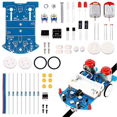
ICStation tracking robot car is widely used in school robotics and electronics education competitions, you can have a lot of fun and learning putting this robotics kit together and understanding the theory behind the way the Light Dependent Resistors detect the difference between the black of the line and the white of the area outside the line, if you're helping a youngster put this kit together you can instruct them in reading the resistor codes or using a multimeter to identify the ratings of the resistors so placement on the PCB is correct.
Please pay attention to the patterns on PCB, the resistances with different color rings, the polarities of capacitances, LEDs, and the mini gap on the chip, you will find the right placements. When finish assemble them, please practice to seal components to each bonding pads with own solder wires.
Installation Steps:
(1) Install metal film resistor, DIP-8P IC socket, Self-Locking switch, Potentiometer, S8550, Electrolytic capacitor, 5mm Red LED on PCB according to mark on PCB. Notice please: Pay attention to the direction of IC Socket. In addition to facilitate debugging, don't install IC LM393 temporarily.
(2) PCB placed in front. The support bolts of the caster are inserted into the hole, tighten the nuts screwed into the caster, and finally fit the caster and tighten.
(3) Install photoresistor and white LED on PCB reverse. But please make sure the distance is about 5mm between top of mecanum wheel (top of screw cap top) and photoresistor/ LED.
(4) Install 2pcs DC motors.
(5) Install battery case and wheel
(6) Test:
(6.1) Install your 2pcs AA battery.
(6.2) Press on switch. If 2pcs white LED ON, the installation is successful. If LED off, please check the welding. Pay attention to the direction of LED and other component and check pseudo Soldering.
(6.3) Power on. Check S8550 or 10ohm resistor if motor don't move.
(6.4) Install LM393 (Pay attention to the direction of IC).
Soldering Practice Kit Electronic DIY Project Line Following Car DC Motor STEM Learning Project
Was:
$67.88
Now:
$33.94
- SKU:
- M210897
- Condition:
- New
- Availability:
- Free Shipping from the USA. Estimated 2-4 days delivery.


